Uplink (TX): any frequency (144-146 MHz, 430-440 MHz etc.), FSK-modulation
4800 up to 19200 kBaud,
Downlink (RX): 430-440 MHz, 38400/76800 Baud FSK (153 kBaud with wider filters
(optional)).
Download installation manual for IFD for FT847
Material required:
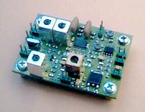
| SYMEK IFD-B-amplifier-mixer-demodulator board option 'FT847' | |
| 2x30cm thin coax cable, wire, shielded audio cable and other hardware, heatshrink tube etc. (included) |
1. Transmitter (modulation) and PTT (transmitter keying):
Check the manual how to operate the transmitter in 9600 Baud FSK mode and the PTT line.
3. Demodulator output:
We have modified this type of transceiver with good results, according the schematics of the service manual, there should be no major problems to insert the IFD in the rf signal path of the FT 847.
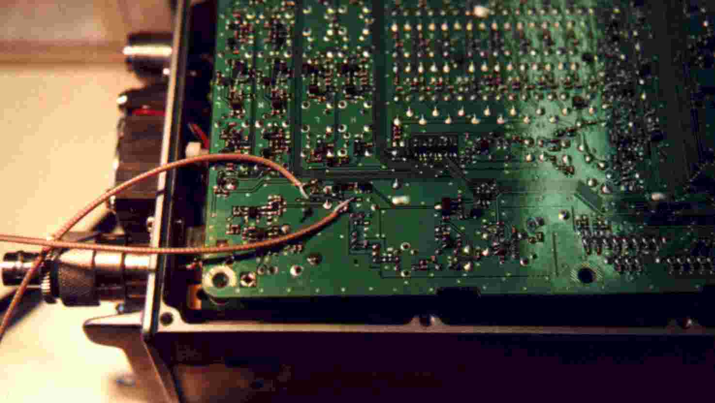
Find the main receiver board. There is some shielding box in the upper right corner, which includes the 1st mixer and associated parts.
(Picture of the main receiver board + magnified view of the mixer box shown in printed version)
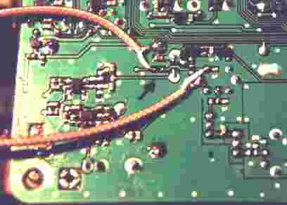
(Picture of the component location plan with arrow where to add the coax wires (printed version only))
 click to magnify
Location of the chip capacitor C3371 in the chip side of the printed circuit board
![]() click to magnify
click to magnify
Schematics: 1st mixer / Front end 440 MHz
Here you see the transceiver front end: left side the balanced mixer, middle the balun with ist 50 Ohm output and right the transformer which matches the 50 Ohm to the quartz filter input. The IFD has to be inserted in the 50 Ohm signal path between the balun output and the resonant transformer circuit. Remove simply the coupling capacitor C 3371 (10 nF) and connect a 50 ohm coaxial to each end of the removed capacitor.
The wire at the balun output is marked 'mixer' and goes to IFD input. The other wire marked 'filter' returns the rf from the IFD to the 50 Ohm input of the transformer and the quartz filter. Solder the shield of both cables to a ground plane nearby. Make sure not to short circuit the signals unintentionally.
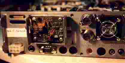
There is NO space in the transceiver case to install the IFD. Try to install it at the rear panel.
 click to magnify
If you remove the loudspeaker, it is possible to install the IFD there.
You have to install 4 connections to the IFD board:
1. solder the coax cable "mixer" to the RF-IN (terminal M1) (shield to M2)
2. solder the coax cable "filter" to the RF-OUT (terminal M11) (shield to M12)
3. solder a red wire to terminal M90 (+12V). The other end of this wire is soldered to permanent 12Volt internal supply.
4. The demodulator output (terminal M63, data out) goes to a spare pin of an acessory connector and to the 'demod' input of a receiving packet-radio-controller with 38400 Baud receive modem. Use a thin shielded audio cable.
5. Ground connection for power supply is not necessary in most cases as cable shields are already grounded at the other end.